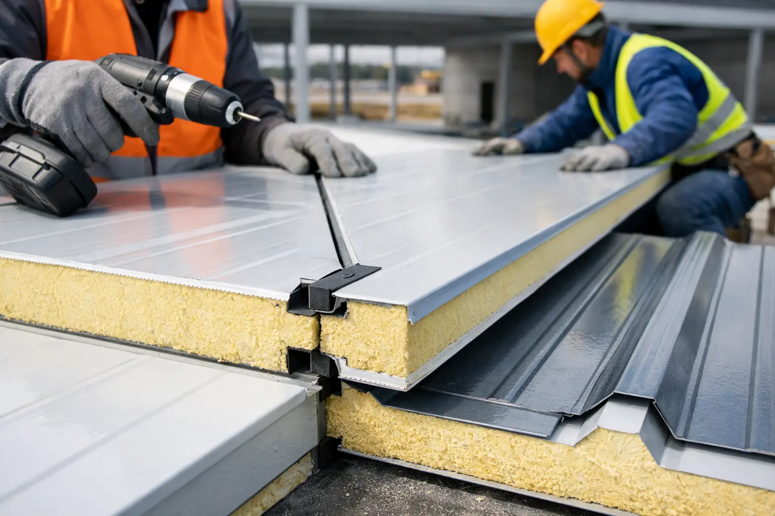
A panel can meet the required insulation thickness and still underperform if its joints are poorly detailed. This sandwich panel joint detailing guide focuses on the areas where water, air leakage, heat transfer, and installation errors most often begin: panel laps, perimeter interfaces, penetrations, and flashing connections.
For contractors, fabricators, engineers, and procurement teams, joint detailing is not a finishing item. It should be considered before panels arrive on site, alongside panel orientation, support spacing, fixing layout, flashings, sealants, and accessories. A clear approach helps protect the building envelope and avoids expensive corrective work after installation.
What a Sandwich Panel Joint Must Achieve
The purpose of a joint changes slightly between a warehouse roof, an external wall, and a cold storage enclosure, but the basic requirements remain consistent. The joint must connect adjacent panels securely, manage water correctly, reduce uncontrolled air movement, and maintain continuity of the insulated envelope.
In roof applications, weather tightness and drainage are the first concerns. Water should always be directed outward and down the roof slope, with no exposed route into the side lap or end lap. In wall cladding, the detail must handle wind-driven rain, building movement, and a neat visual finish. For cold rooms and cold stores, airtightness and vapor control become especially critical because warm, humid air entering the enclosure can lead to condensation and reduced thermal efficiency.
The panel profile, core type, thickness, building use, and local exposure conditions all affect the final detail. A standard joint detail should therefore never be copied blindly from one project to another.
Sandwich Panel Joint Detailing Guide: Start Before Installation
Good detailing begins with coordinated information, not with sealant applied after a leak appears. Before installation, confirm the approved panel layout, roof pitch where relevant, panel direction, support locations, opening positions, and the required flashings.
The installation team should also verify that the selected accessories are compatible with the panel system. This includes butyl tape, foam closures, sealing strips, fasteners, stitch screws, ridge caps, corner flashings, gutters, and trims. Substituting an accessory without checking its function can create a weak point at the joint.
Panel lengths should be planned to limit unnecessary transverse joints. Fewer joints can simplify installation and reduce potential leakage paths, although transport access, lifting capacity, and site handling may make shorter panels more practical. The right balance depends on project conditions.
Check Panel Alignment and Support Lines
A clean joint relies on accurate alignment. If the first roof or wall panel is out of line, each following panel can amplify the error. This may leave inconsistent joint widths, make flashings difficult to fit, and place uneven stress on the panel edges.
Support lines must also be set out correctly. Fasteners installed away from the intended purlin or rail location may not provide the required holding capacity and can deform the panel face. Confirm structural drawings and panel supplier recommendations before fixing begins.
Keep Joint Surfaces Clean and Dry
The male and female edges of insulated panels need careful handling. Dirt, metal swarf, moisture, damaged protective film, or crushed insulation at the joint can prevent panels from seating properly. Sealant applied onto contaminated surfaces is less likely to form a reliable bond.
Store panels off the ground, protected from standing water, and with adequate support to avoid edge damage. Remove protective film in a controlled manner during installation so it does not become trapped beneath trims, sealants, or flashings.
Detailing Longitudinal Joints
Longitudinal joints run along the length of adjacent panels. On a roof, these side laps are exposed to rain and should interlock fully before fasteners are installed. The panel should not be forced into position with excessive pressure, as this can damage the profile or leave the joint uneven.
Use the specified sealant or tape continuously where the panel system requires it. Gaps in a sealant line, poorly joined tape ends, or sealant placed on the wrong surface can create a direct route for water. At roof laps, sealant placement must work with the profile geometry so that water is kept on the external drainage side of the joint.
Wall panel joints require similar care, particularly where panels are installed horizontally. The joint orientation should shed water rather than hold it. Vertical wall panels often simplify drainage, while horizontal panels may require closer attention to lap direction, intermediate supports, and joint sealing.
Do not rely on external sealant alone to compensate for a poorly engaged panel joint. Sealant is part of the system, not a substitute for proper panel fitment.
End Laps, Roof Transitions, and Ridge Details
End laps require more attention than continuous side laps because water crosses the joint line. They are commonly used when panel length is limited by transport or installation constraints. The overlap length, sealant arrangement, fastener pattern, and minimum roof slope should follow the approved panel-system details.
At an end lap, the upper panel must overlap the lower panel in the direction of water flow. Sealant should be continuous across the lap, including around profile ribs where required. Fasteners need consistent spacing and correct tightening. Over-tightening can distort the outer sheet and damage the sealing washer, while under-tightening can leave the connection loose.
Ridge details must close the top of the roof without obstructing ventilation or drainage requirements specified for the building. Ridge caps should overlap adequately and be sealed at their laps. Profile fillers or closures may be needed beneath ridge flashings to prevent wind-blown rain, dust, insects, and birds from entering the roof cavity.
Where the roof meets a parapet, higher wall, or adjoining structure, use purpose-made apron flashings and upstands. These areas are often exposed to water buildup, so the flashing must extend high enough to suit the roof geometry and expected drainage conditions.
Wall Corners, Base Details, and Openings
Wall joints are only as reliable as their perimeter connections. At external and internal corners, panels should be cut accurately and covered with suitable corner flashings. The flashing must provide a finished appearance while protecting exposed panel edges and sealing the interface.
At the wall base, provide a detail that prevents water from entering behind the panel. Base channels, starter tracks, closures, and flashings should be selected according to the wall construction and whether the panel sits above a slab, curb, or foundation beam. Allowing direct contact between exposed steel edges and persistent standing water should be avoided.
Door, window, louver, pipe, and service openings need coordinated trim details. Cutting panels on site is sometimes necessary, but exposed cut edges should be protected promptly with the appropriate flashing or trim. Penetrations should be kept clear of major panel joints where possible. A penetration placed directly on a lap complicates sealing and makes future inspection more difficult.
Cold Room Joints Need a Different Level of Control
Cold room and cold store panels require carefully sealed joints because even small air leaks can permit moisture-laden air to enter the insulated enclosure. This can cause condensation, ice formation, and localized loss of thermal performance over time.
Use the joint configuration and sealing materials specified for the cold room panel system. Pay particular attention to floor-to-wall connections, wall-to-ceiling junctions, ceiling panel joints, door frames, and service penetrations. These are common locations for discontinuities in the insulated and vapor-controlled envelope.
For refrigerated spaces, it is worth planning services early. Late additions such as refrigerant lines, electrical conduits, or drains often lead to field-cut penetrations that are harder to seal correctly. A coordinated penetration layout reduces rework and gives the installer enough space to apply trims and sealants properly.
Common Joint Detailing Mistakes to Avoid
Most joint failures are preventable. The recurring issues are usually related to poor sequencing, incompatible materials, or rushed workmanship rather than the panel itself.
- Installing panels in the wrong overlap direction, allowing water to run toward the joint opening.
- Leaving gaps in butyl tape, sealant beads, foam closures, or flashing laps.
- Using damaged panels with bent edges, crushed cores, or distorted joint profiles.
- Fixing before panels are fully engaged, aligned, and supported correctly.
- Cutting openings without protecting exposed edges with suitable trims or flashings.
- Using roof and wall accessories that do not suit the panel profile or project environment.
A final inspection should include visual checks from both inside and outside the building where access allows. Look closely at ridge caps, gutters, roof penetrations, wall corners, door openings, end laps, and transitions between different materials. These interfaces deserve more attention than the uninterrupted center areas of a panel run.
Specify the Full Joint System, Not Only the Panel
When requesting a quotation or preparing a material schedule, identify the joint-related accessories as part of the package. Panels, flashings, ridge caps, gutters, sealing materials, closures, fasteners, and trims should be coordinated from the start. This improves material compatibility and helps avoid site delays caused by missing small but essential items.
For projects across the UAE, exposure to heat, dust, occasional heavy rain, and coastal conditions in some locations should be considered during design and material selection. The correct detail depends on the building's use, location, roof geometry, and the selected panel system.
Before releasing a sandwich panel order, review the joint drawings with the installer and confirm that every roof edge, wall termination, opening, and penetration has a practical detail. MetalSpan can support contractors and project teams with suitable sandwich panels, flashings, and accessories so the complete envelope is planned as one coordinated system.